

- Jon
Questions
9
Answers
8
-
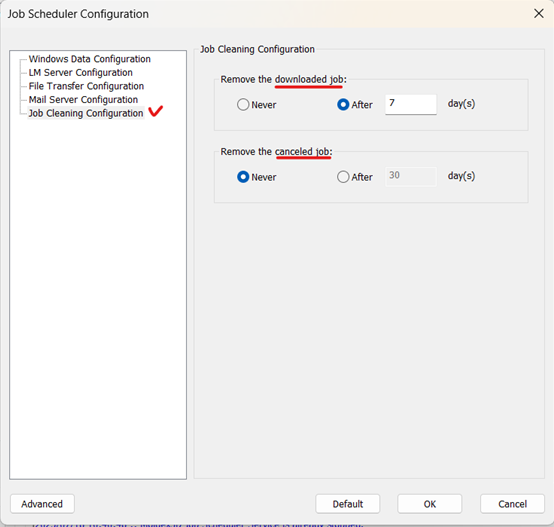
Yes, is possible to automatically delete the downloaded and canceled job on calculation server.
You could try to control it by the “Job Schedular” of the calculation server.

Firstly, stop the server and go for “Service Configuration”.
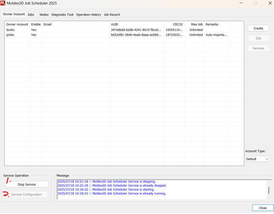
Then, in the “Job Cleaning Configuration” section, they could control the automatic removal time of the job has been downloaded or canceled.
Once the configuration has been done, don’t forget to “Start Service” again.
- 416 views
- 1 answers
- 0 votes
-
The function “measuring face” would only work on surface mesh.
To achieve your purpose, there could be two ways to work it around.
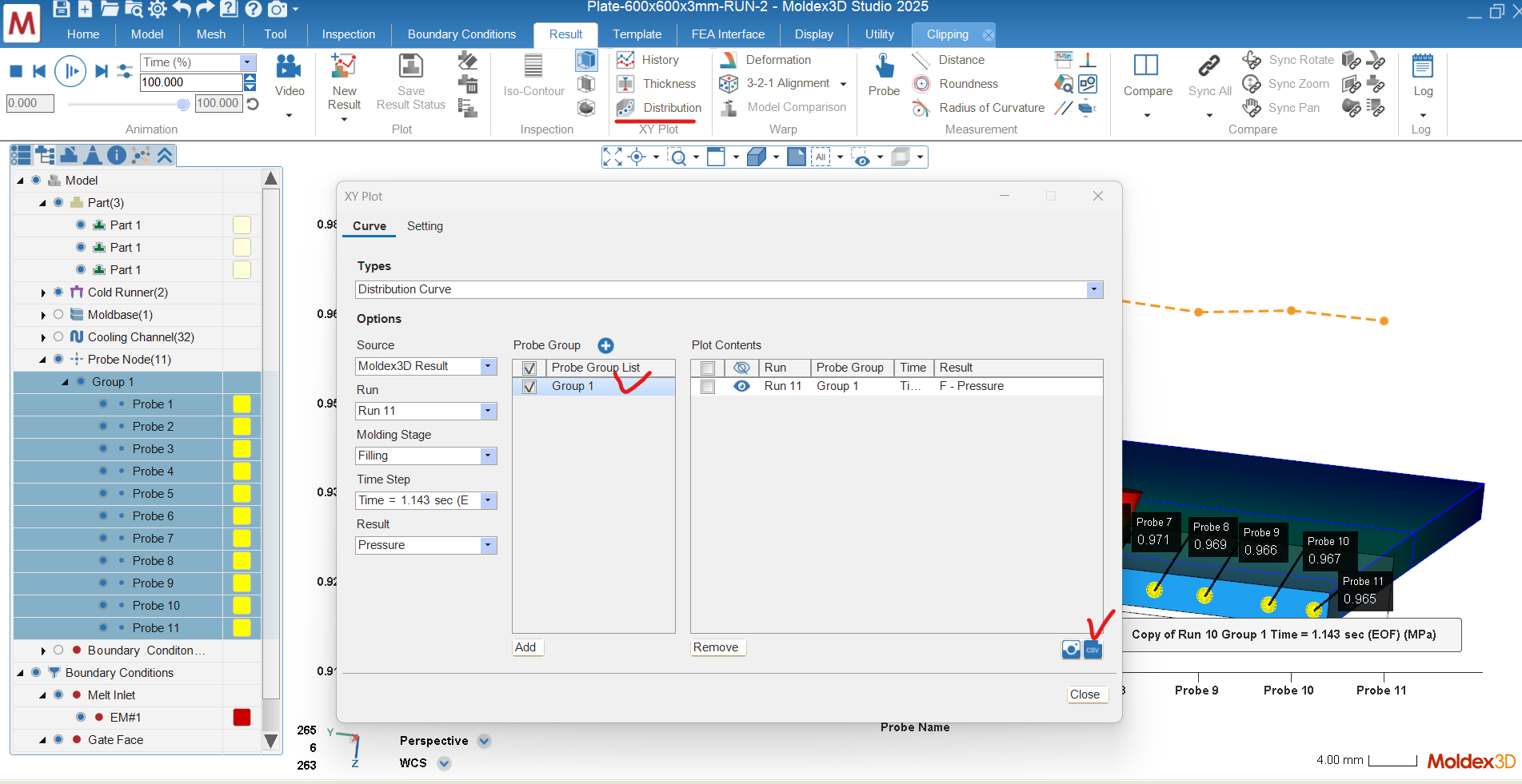
1.Scatter multiple probes and find the average value of the probes
The probe function is supported in both clipping and slicing functions
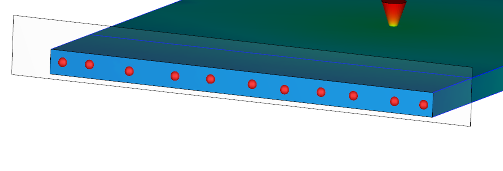
Users could use the “Distribution” function, add the group of probes, show the target result and export it as CSV file.
Utilize the data in CSV file to calculate the average value
2.Separate the geometry in the area you want to observe in pre-processing
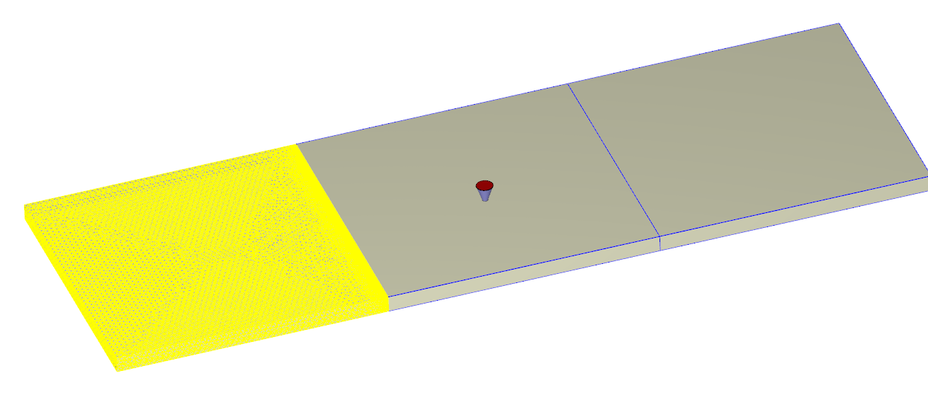
So, you could utilize the “Measuring Face” to estimate the average value of the target surface.
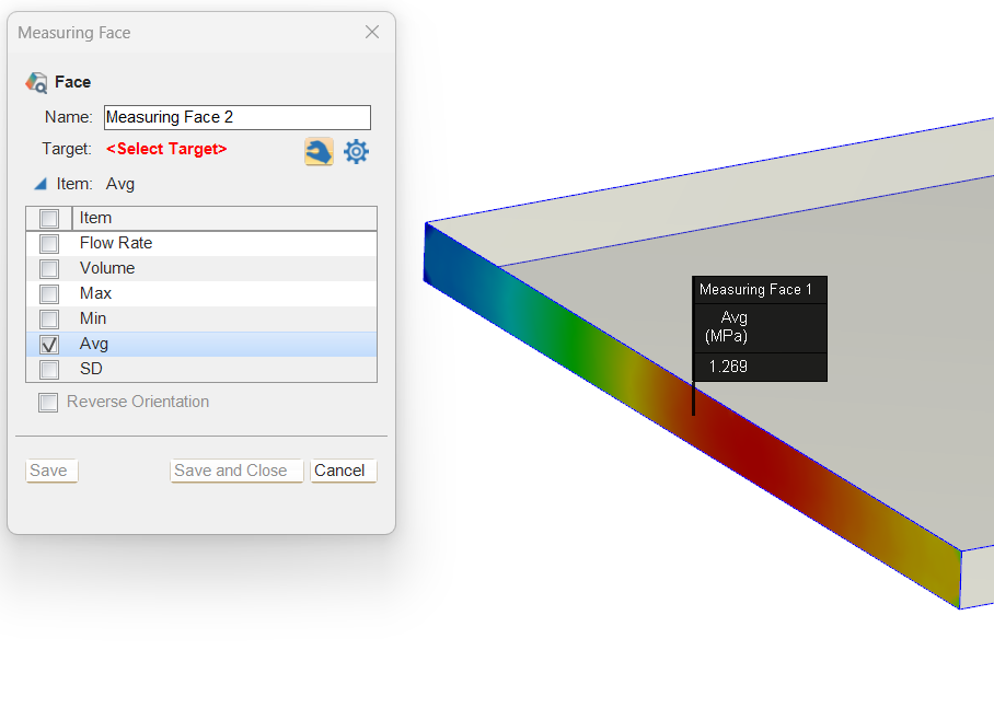
Please note that the surface mesh between two separated parts needed to be matched with one another.
- 589 views
- 1 answers
- 0 votes
-
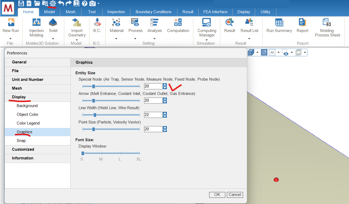
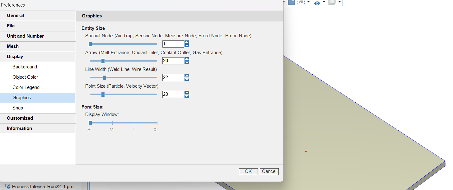
Yes, you can adjust the size of the display items in the “Preference” settings.
Users could find the “Display” section and go for “Graphics”.
For example, the size of probe could be control by the “Special Node”.
- 621 views
- 1 answers
- 0 votes
-
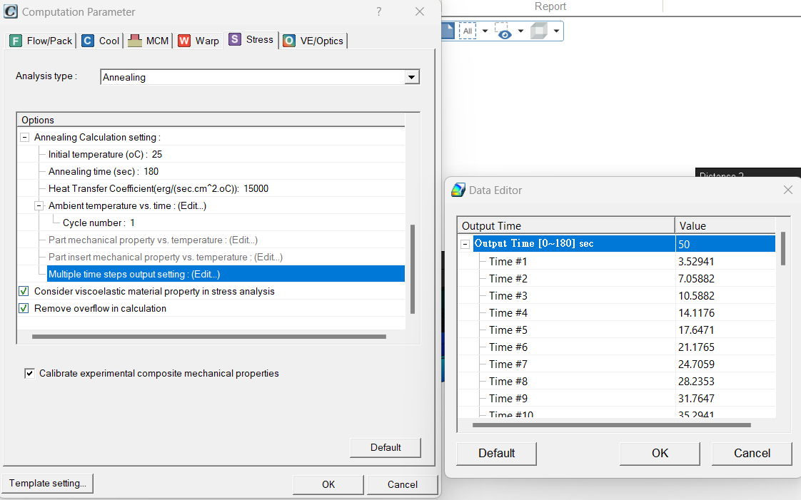
This type of simulation can be performed using the annealing solver, which is included in the Stress module of Moldex3D.
Steps to Perform the Simulation:
- Select the annealing solver under the “Stress” tab in the computation parameters.
- Set up an ambient temperature profile (e.g., simulating a heater) for a specific period of time.
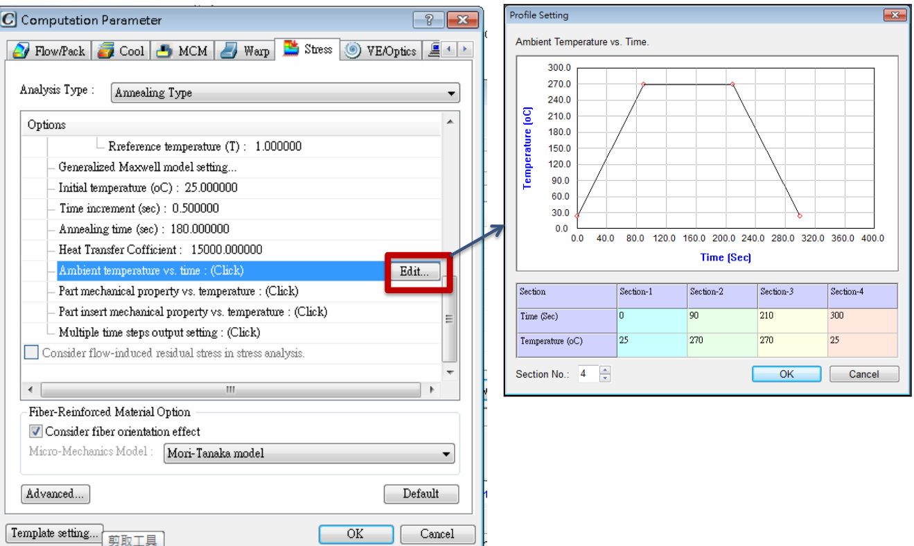
Important Notes:
- Configure enough time step outputs during the heating, maintaining, and cooling stages.
This affects the number of observable time steps and the calculation precision.
- The time increment of the annealing simulation also takes time steps into account, so proper configuration is crucial for accuracy.
- 516 views
- 1 answers
- 0 votes
-
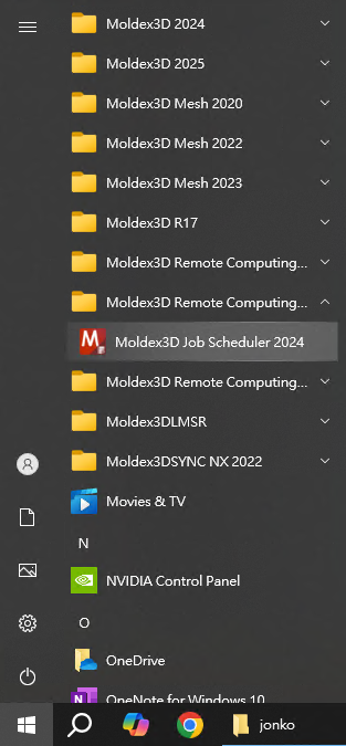
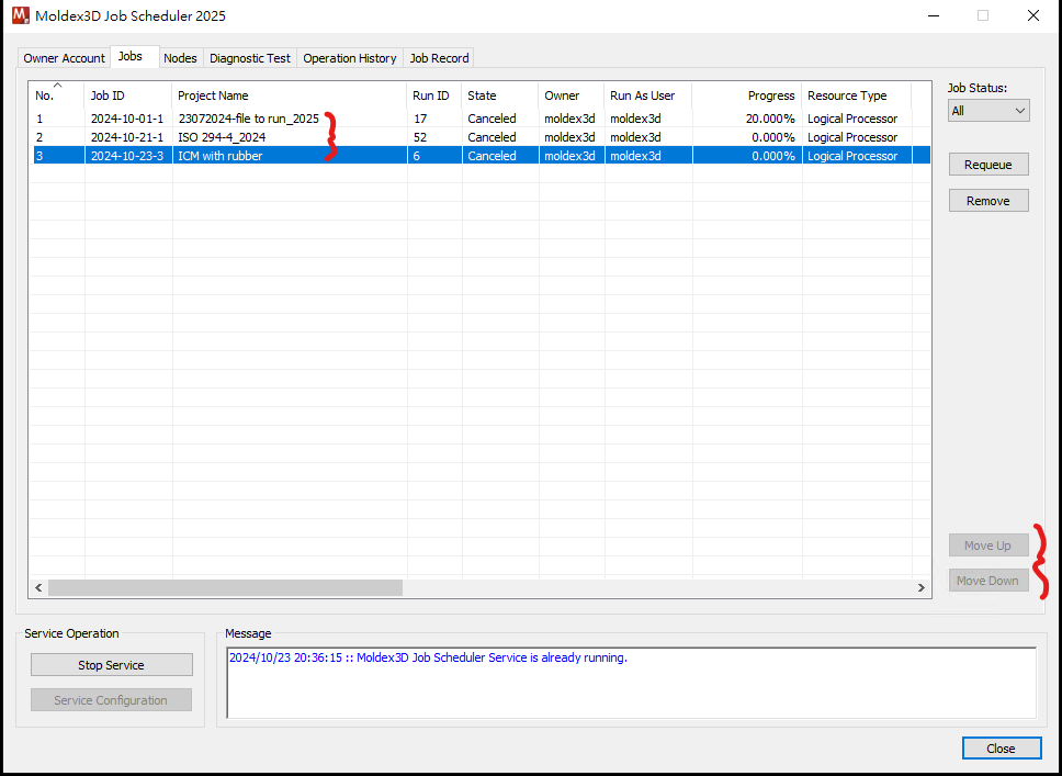
We could manipulate the order of the runs in queue by the Job Schedular.
Users could go for the Job Schedular of the computing server.
In the “Jobs” tab of the schedular, all the runs in simulation and in queue could be observed.
Users could use the Move Up/Down functions to rearrange the queuing order of the jobs.
- 598 views
- 1 answers
- 0 votes
-
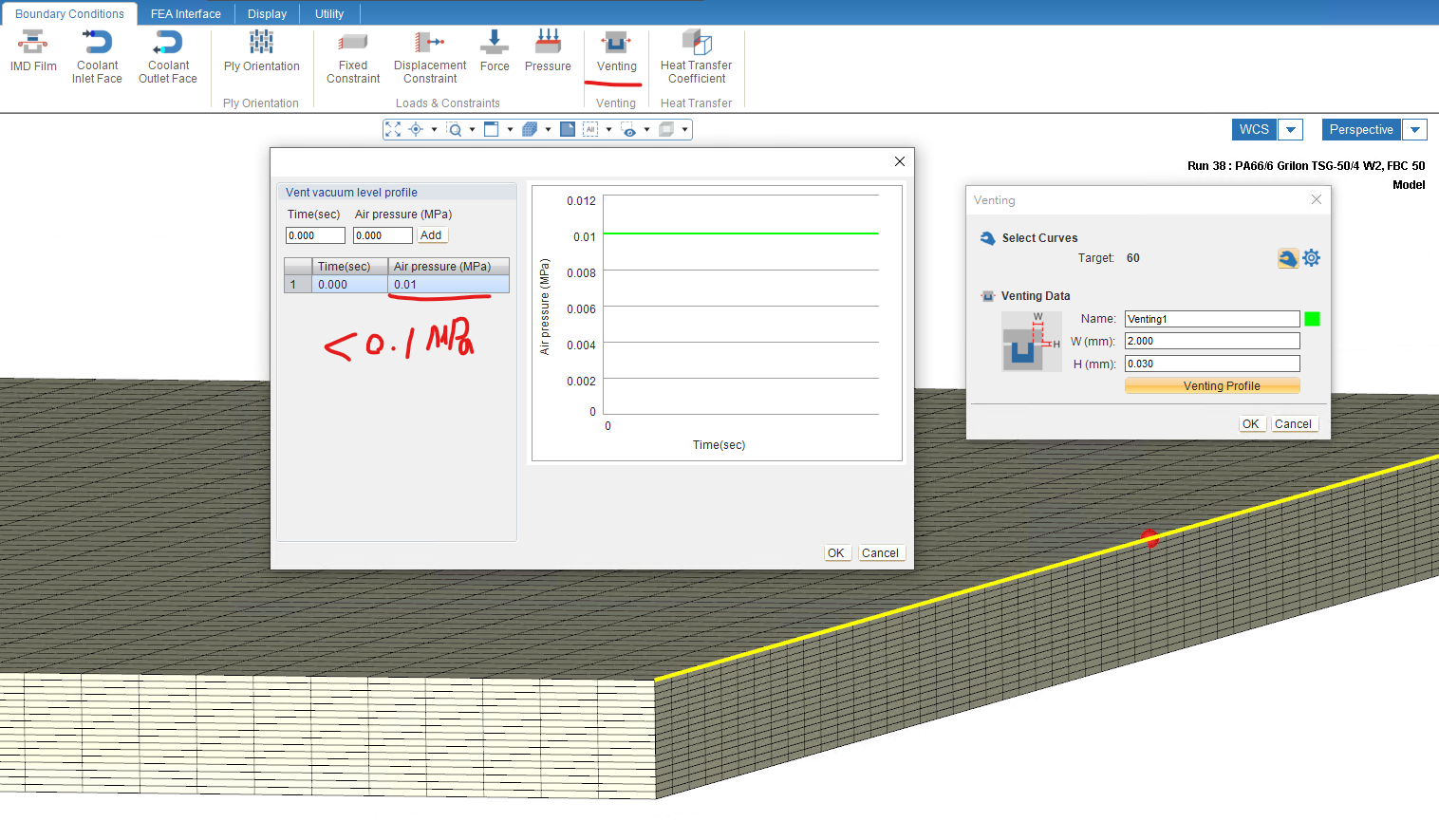
Yes, a vacuum system could be considered by the venting BC setting.
Users could go for the Venting function in “Boundary Condition” tab.
Both the feature line of the geometry and the edge of the mesh could be chosen as a boundary.
In the setting profile, you could setup an air pressure that is lower than 0.1 MPa (atmospheric pressure) and the solver would consider it as a vacuum BC.
- 881 views
- 1 answers
- 0 votes
-
To generate a report with customized results one could,
- Export a PPT report by Moldex3D report wizard by the General Template. The results would be shown as the status that “Save Result” saved. The “New Result” would be shown at the end of the report with the order in the Studio UI
- To export a customized template, one could use the tag “#Result_Customized#%id%” to export the designated “New Result”. For example, I want to export the image of new result ID #2 (check the UI). I could write “#Image_Result_Customized#2” in my PPT corresponding slide.
- 583 views
- 1 answers
- 0 votes
-
Until Moldex3D 2024, to utilize the auto-meshing kernel, the basic limitations is,
-
- Auto-hybrid only support +Z direction generation
-
- All components should be columnar shape (no curvature along z direction)
-
- All components should not overlap with one another (except epoxy)
It’s recommended to prepare a 2D layout of the geometry design. (Moldex3D Studio also provides CAD tools to extract the 2D features from the geometries)
- 792 views
- 1 answers
- 0 votes
-


